Rostra Cruise Control module switch settings may differ if you use a speed signal generator or magnets. A Rostra control switch will have to be used if you have a three wire GM switch.
 Power Window Wiring Diagram 1 Power Diagram Windows
2004 Chevy Silverado Power Window Wiring Diagram Free Engine Wire Center.

Gm cruise control button wiring diagram 1. This unit will only work on four wire GM switches. Cruise On Signal- This is simply an on off switch that enables or disables the cruise function. Momentary meaning it only sends 12v.
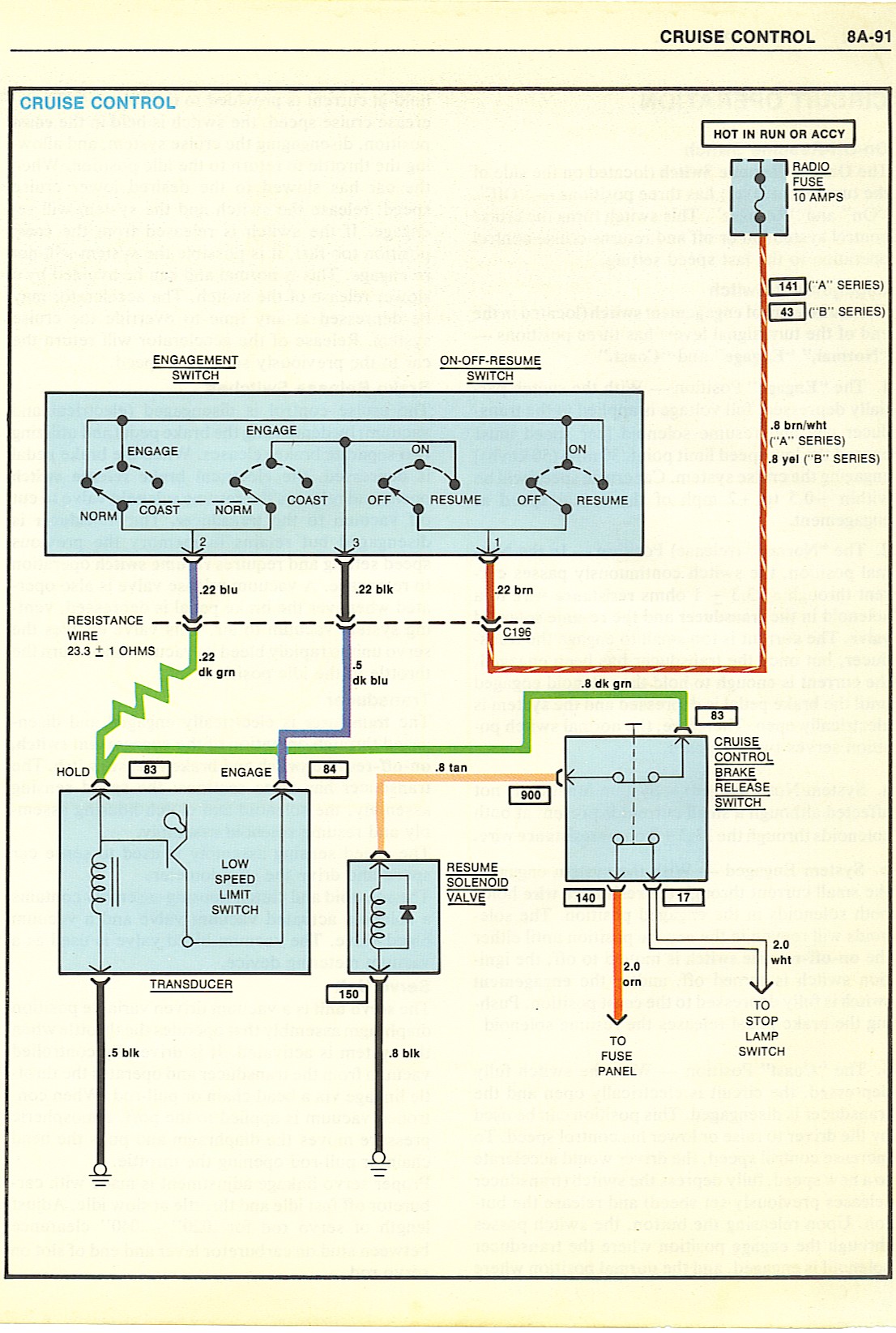
Cruise wire is hot when key is on and as far as I can trace it it becomes a gray wire at the cruise disengagement which goes into the under dash harness that I cant follow. A normally closed 12V switch applies power to the clutchbrake switch input pin D and a normally open 12V switch applies stop lamp voltage to the. The Global Cruise is designed to work with most cars trucks and SUVs equipped with a mechanically-operated throttle.
For example the wiring diagram for a Ford EEC-IV system may be included in ENGINE PERFORMANCE and WIRING DIAGRAMS articles for Ford Motor Co. Wire 139C at this splice is addressed to R4. Vehicles with Manual Transmission require Clutch Switch.
Chevrolet Car Wiring Diagram - Corvette Bel Air Cavalier Impala Camaro Astro Malibu Venture Chevelle PickUp Suburban Tahoe Sonoma. CHEVROLET Car Manuals PDF. Heres the power flow From Battery to 107 40A fuse in the battery junction box.
Cruise control activator connector. Item Accessory 1 2 3 Conflicts STOP STOP. 250-2766 1 Pedal Interface Harness 5.
250-2763 1 Cruise Control Module 2. It is the 08 PNKl8lK wire. This is not a description of how to install these features if not ordered as part of the option.
The Painless wire harness is designed to be used in vehicles with a General Motors - keyed steering column or other steering columns depending on the kit purchased. See Chapter 15 Project 1 on page 112 to see an early GM steering column with only a setcoast cruise control switch Brake Switch. At location code R4 wire 139C is the 08 PNKlBLK wire to terminal C of the speed sensor connector.
I need a wiring diagram of the cruise control and under dash to fix my speedo. Self-learning calibration makes this system a snap to use with no DIP switches or charts to follow. The GM UF3 option described here is the necessary electrical and electronic content to control the engine idle speed.
Soon after Durant was forced out of GMs he began to cooperate. Some vehicles may require a speed signal generator andor other partsadapters not listed above. All wire is 600 volt 125c TXL.
250-2759 1 Main Wiring Harness 4. Direct plug-in cruise control for GM LS drive-by-wire engines the CRC Series plugs directly into your OEM LS throttle pedal for not only simple installation but reliable operation and connectivity. The code at this location refers back to the splice at N9.
Universal and Custom Cruise Control Switches by Rostra. Power flows through fuse 107 to ignition switch and terminal 87 in the starter relay socket. Dome lights stay on May 7 2013.
250-3742 1 Control Switch Note. Chevy silverado window wiring diagram 2002 power chevrolet 1992 gmc 2018 gm truck harness electric troubleshooting 1999 door 2008 lock switch 2000 2005 trailer it has 1967 corvette 2004 2007 trailblazer mirror for camaro 01 2001 yukon drivers side will not work 2003 tahoe colorado canyon forum up windows and locks f150. Click on the jpg to download the wiring diagram of the starter circuit.
After set each quick press of the switch will lower set speed 1 mph. A three wire switch will not work with this unit. The Global Cruise cruise control system by Rostra was developed with safety and flexibility in mind.
Control Switch Wiring GM original cruise control switch open circuit style switch. Three wire switches can be found in some 1974 and older vehicles. Brown wire at cruise control is supposed to go to brown wire A16 at the instrument cluster plug.
The address at this location refers back to the splice at N9. Rostra manufactures a number of different control switches for cruise control operation so youre sure to find one that. When IGN switch is turned to START power flows to Read More.
The cruise control module requires two brake switch signals. Chevrolet cars coproration was founded in 1910. Gm ignition module wiring diagram another picture.
The wiring diagram for a cruise control system may be included in ACCESSORIES EQUIPMENT section for the specific vehicle manufacturer and the wiring diagram for an anti-lock brake system may be. 250-2767 1 Hardware Kit 6. Cruise ResumeAccel Signal- This is a momentary switch signal which sends 12v down this wire.
Damage to the vehicle may occur. When you employ your finger or the actual circuit together with your eyes its easy to mistrace the circuit. 250-2760 1 Switch Harness 3.
This needs to be switched 12v to this wire. Image result for what wires go where when hooking from the gm cruise control wiring diagram fokus fuse12 klictravel nl safety switch wiring diagram how to test a neutral safety.
 Car Condenser Fan Wiring Diagram And Honda Civic Cooling Fan Wiring Wiring Diagram 17 Car Condenser Fan Wiri Electrical Wiring Diagram Honda Civic Diagram
 Gm Cruise Control Wiring Wiring Diagram Electron Venus Electron Venus Hoteloctavia It
 The Poor Man S Start Interrupt Switch Non Obvious Way To Disable Starting Motor Vehicle Car Audio Installation Electrical Projects Basic Electrical Wiring
 Pin On Wiring Diagrams
No comments:
Post a Comment