3 phase rotary switch wiring pole 4 way diagram six for two three change over switches selection guide motor control selector home cam 1970 untitled 2 position uno dptt schematic hack a week 630b practical machinist largest converter using single power gang the gear page vertical double door db auto start kan nie how to wire car. After this diagram i hope now you will be able to connect a portable generator to house load.
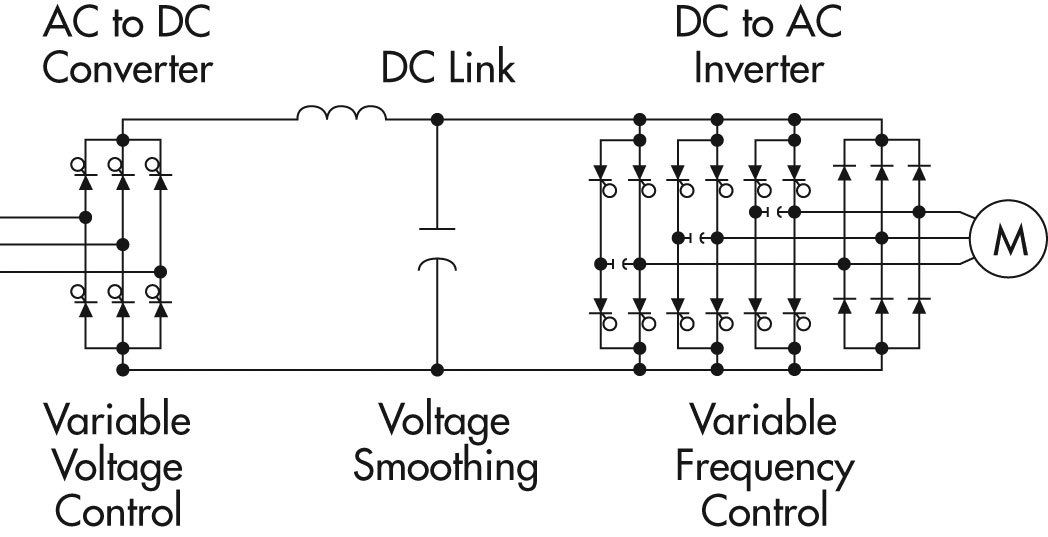 Principles Of Operation Ac Vfd Drives
Some rotary switches contain more than one circuit.
Wiring diagram 3 position and two 3 phase vfds. 2 Humbuckers3-Way Toggle Switch1 Volume3 Mini Switches for Series-Split-Parallel on Each Humbucker Master Series-Parallel. Please not that whenever two leads of a three-phase power supply are switched the phase relationship between these two leads is changed and the motor will run the opposite direction. From NEMA standard ICS 2-321A60 1-Phase 2-Phase 4-Wire 3-Phase Line Markings L1 L2 L1 L3.
In the above diagram the black color denote the neutral wire red color denote the phase wire Line Hot wire and Green color denote the earth ground wire. Functions Of Motor Control Selector Switches Electric Equipment. Below is a given schematic wiring diagram fig 2 that shows how to wire a 2-way switch and control a light bulb from two different places.
1 The VFDs three phase AC input terminals rl1 sl2 tl3 The power lines input terminals connect to 3 phase AC power through line protection or leakage protection breaker it does not need to consider the connection of phase sequence. 3Hp VFD with a 3Hp motor then anything above 3Hp must use 3 phase power. VFD says its Input200-240v 5060hz 3-phase 196amps But all i have available as Input is 110-120v or at max 200-240v 1-phase Not Input200-240v 5060hz 3-phasehow would that work.
Main circuit wiring The VFD main circuit terminals shown as below Figure. Our wiring techs can design a custom wiring diagram for any brand and type of pickups with your choice of. Need Help Wiring 3 Position Selector Switch For Brewtroller Home within 3 Position Selector Switch Wiring Diagram image size 640 X 480 px and to view image details please click the image.
With the phase switch. 2 Humbuckers3-Way Toggle Switch1 Volume2 Mini Switches for Dual Coil Tap of Both Humbuckers. Wiring Diagram Book A1 15 B1 B2 16 18 B3 A2 B1 B3 15 Supply voltage 16 18 L M H 2 Levels B2 L1 F U 1 460 V F U 2.
3 MIDDLE SHEET 2 460 VAC 3Ø 60 HZ GRNYEL YELLOW WHTRED RED GRAY WHTBRN SEE THE LAST SHEET FOR LEGEND WARNINGS AND NOTES. This is an important feature of VFDs in that they can reverse the direction of the motor without using expensive reversing motor starters. Single-phase wiring diagrams always use wiring diagram supplied on motor nameplate.
Can i use that 5hp VFD to run the 24HP Pump motor. Figure 2 Enable Circuit When the machine is enabled the 24-EN signal turns on. For each additional VFD needed.
1 Phase Input - 3 Phase Output 252 items 3 Phase Input - 3 Phase Output 4034 items 1 3 Phase Input - 3 Phase Output 69 items. ABB two contac-tor bypass systems can perform all three modes of operation without the three position switch third contactor and associ-ated wiring. These contain two or more input terminals called poles.
This turns on RC2 which then connects 230 VAC to the coil of RC1. If your VFD is rated for your spindle motor ie. In this video we used the very popular Mitsubishi D700 series VFD showing single phase and three phase wiring instructions.
2 Humbuckers3-Way Toggle Switch1 Volume1 ToneCoil Tap Reverse Phase. The VFDs showed in the video are the D720S 230V single phase and the D720 230V three phase. For instance when a module will be powered up and it sends out a new signal of half the voltage in addition to the technician does not know this hed think he offers a.
Guitar wiring diagram with 2 humbuckers 3-way toggle switch one volume and tone control plus one pushpull switch to select humbucker or single coil mode and one pushpull switch to select reverse phase for the neck pickup. WIRING 2 OR MORE VFDs WITH 1 CPC-3 BLACK ORANGE BLACK ORANGE The System Schematic for wiring 2 VFDs s hould consist of 3 sheets. But no one sells 15hp single phase VFDs only the 3 phase input ones.
The blue dashed line in the diagram below shows the 3 phase wire. Here is a picture gallery about 3 position selector switch wiring diagram complete with the description of the image please find the image you need. Learn the basic wiring of variable frequency drives VFD with our electrician Steve Quist.
The electricity enters the rotary switchs input terminal and the switch sends electricity to the output terminal selected. A rotary switch connects several devices to an electric source. VFD mode AND Bypass mode as they imply power the motor through one of the two parallel paths.
A FIRST SHEET this MIDDLE SHEET and a LAST SHEET. Begingroup You should shrink some pictures down and show the wiring and nameplate information but red black and blue are standard 3 phase colorings for 120208V 3 phase so each pair are probably the ends of a max 230V coil of which there are 3 so if your source had 220V phase to ground youd set the motor up in Wye and if it had 22345V phase to phase youd set it up in delta. Here i have an image of handle type manual changeover switch which capture with my mobile.
Phase 2 L1 L2 L3. Position 1-2 3-4 A B Push Button Free Depressed Free Depressed contact closed. Three contactor systems are often specified with a three position selector switch VFD-Test-Bypass.
We strongly recommend using a certified electrician to set up your VFDs. The same purpose can be achieved by using the following two way switching connection in fig 3 as well. Phase 1 L2 L4.
 3 Phase Induction Motor Speed Controller Circuit Homemade Circuit Projects Motor Speed Electronics Circuit Circuit Diagram
 What Is Ac Drive Working Types Of Electrical Drives Vfd Diagram Circuit Design Electronics Components
 Unique Wiring Diagram Baldor Electric Motor Diagram Diagramsample Diagramtemplate Wiringdiagram Diagramch Electric Motor Marathon Electric Marathon Motors
 How To Control Vfd With Push Button Switch Terminal Control Wire Control Youtube
 Ac Motor Control Circuits Worksheet Ac Electric Circuits
No comments:
Post a Comment